Friday, September 25, 2020

SketchUp - free*, and easy to learn

*For personal use, it's free.

SketchUp has been around from years.  Available from Trimble, this seemingly simple tool make creating 3D plans for construction projects, or even a little abstract art, easy once you master the basics.  Rather than put together a tutorial for SketchUp, I thought I would put a little gallery of my projects that I've used SketchUp to design here.  There are plenty of tutorials and videos already.

A set of timber stairs - integrated dead-man not shown.

What I like about SU is that it lets you extrude geometry, keeping things aligned. It has a very intuitive way of simplifying what amounts to basic CAD work with snap points and three axis, intelligent design guides. Sometimes I use it for detailed designs and drawing. Sometimes, just to layout the space in the shop with basic cubes to represent items.

Two different ways to arrange my shop equipment.

Occasionally, I want to build a tool or jig, and using SU to physically experiment with the design helps me think the structure through.  Where will I use screws or fasteners? What sort of materials will I need?

A simple sand and gravel sorter

But the usefulness of SU does not end with just figuring out an assembly.  You can create visual walk throughs for architectural models.  I'm planning to finish my basement, and have created several versions of the SU model, and have used POV screen shots to sell my wife on the idea.


Using the SU parallel projection view mode, I can take an exported image and use it to figure out my materials.  There are, I believe, paid plugins for this if you choose to spend money on the tools, but I have been estimating materials for jobs for my own projects for years and like my method.

Counting 2x4's to purchase (in red)

Thus far, my favorite use of SketchUp has been designing the ongoing landscaping project I've been working on behind my house for the past three years.  The project has been through 8 revisions, with the very early models looking, well, bland and unimaginative, compared to the latest revision.  Using SU to play with designs has saved a lot of time, money, and rework.

First Stab - blaaaah!

Version currently under construction.

It does take some time to get comfortable with SketchUp, and it can be frustrating at times. My biggest pro-tip is to always confirm your snap point is where you think it is.  Many times I've had to go back and fix geometry that was off just a tiny bit.  Creating components is also super handy, and I don't take advantage of it often enough, but it does make moving chunks of geometry around very easy.

Give it a shot. If you've been cooped up all summer and need a creative outlet, this is a pretty decent one to try.

Thursday, January 10, 2019

Upgrading a Retaining Wall

This article is a long time in the making.  In 2017, just before the end of summer, a young man at our church returned unexpectedly from what would have been a lucrative summer working on a fishing boat in Alaska.  Things did not pan out for that adventure, and I wanted to help him out, so I offered to hire him as an independent contractor to help me with some work around the homestead.


What started off as some simple land management quickly took a serious turn.  I realized I had a hard worker on my hands, so I bumped up his pay (twice) and cooked up a really big project, one that I had been wanting to tackle but had only given modest consideration.  That project was to replace the unsafe and not particularly attractive landscape block retaining wall next to the driveway, adjacent to our basement door, with something more functional, attractive, and safe.

Unfortunately, the number of "before" pictures I took were scant.  I happened to catch the view from the garage, behind the house here, where you can see the ground slumps off to the left. The wall is there, just outside the left side of the frame, at about floor level from the garage, totaling about 4 feet in height, with no railing.  I lived in mortal fear of my kids falling off of this wall and getting a broken something.


In my mind, I envisioned taking this stone wall, which curved in from the back corner of the basement, half a floor below the garage, towards the middle left of the picture you see above, and making a straight, tall wall, with a rail along the top.  I was initially undecided on composition and whether there would be stairs, but after getting some quotes for concrete (five figure quotes, I might add) I opted for timber construction.

As with all of my projects, I started off with some SketchUp models.  The final design for the railing didn't really come together until the wall was built.


Construction began with demolition.  I had my hired help tear down the wall and relocate the block for future use. Then we started digging a trench for a compacted gravel footing.  A buddy rented himself and his bobcat to me for an afternoon to help with excavation as we had almost concrete hardness clay to get through, shot through with melon size rocks.


All in all, we wound up moving about 16 yards of material, cutting through the previous layers of grading and gravel that had been dumped to raise the grade after initial construction of the home.  This gravel turned out to be very handy as we sifted it through hardware cloth to make as many loads of compacting material to level the first run of sleepers as we needed.


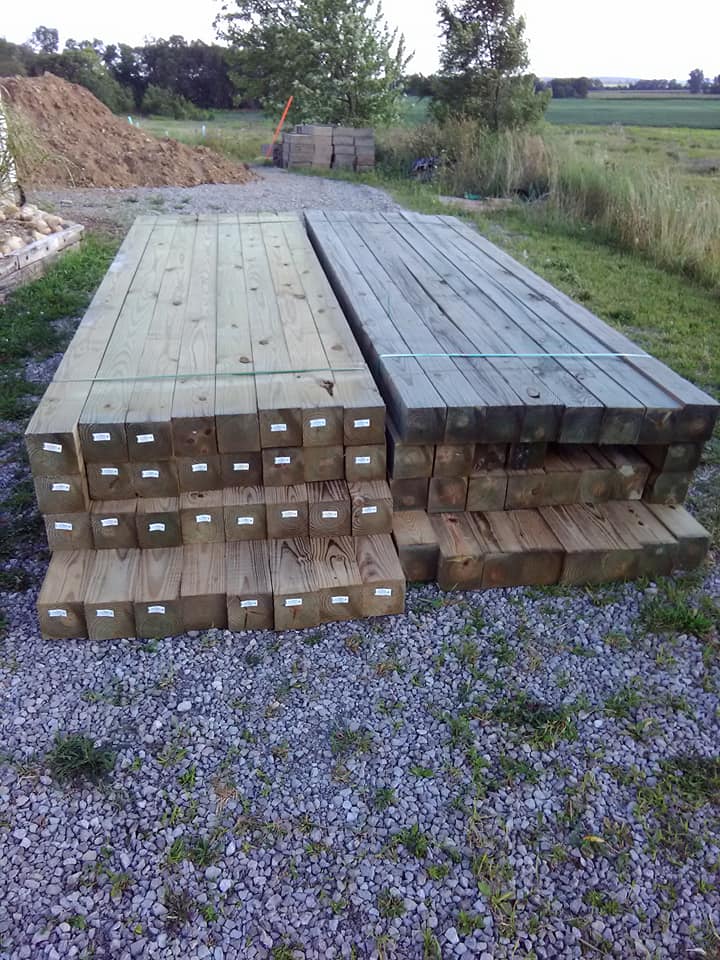
The raw materials took the form of two full bunks of 5.5" x 5.5" x 12' copper arsenic treated timbers.  This is the commercial grade pressure treat chemical that everyone loses their minds about.  Wet, it's something that can be absorbed through the skin and should be handled minimally and washed off soon. Dry, it's very stable and the amount of arsenic likely to leach into the surrounding soil is not much higher than naturally occurring background levels.  I conducted extensive research on this before breaking these bunks apart.


Starting off, we carefully leveled our compacted gravel with a spirit level and tamper.  We double checked our first level of sleepers as we put them down.  These were anchored into the ground with 24" steel spikes to prevent lateral shifts.  


As we began building up the levels, each new level was lag bolted to the preceding one with 1/2" x 8" hot dip galvanized screws.  We used a combination of a socket wrench with a pipe extension on it for heavy torquing and an impact driver with a socket adapter for getting the screws started.  Each screw was placed in a predrilled pilot hole which included a counter sink pass with a spade bit to allow for the 1.5" galvanized washer that we put between each screw and the wood.  This was done to ensure our bolts never pulled through and to provide more grab for snugging down timbers that were not quite true. The project would eventually consume 150 screws and washers of this specification.


As work progressed, we paid attention to routing both the down spout and the curtain drain, each with a final grade that observed a strict down hill flow away from the home's foundation and the rear of the wall.  Also pictured below is the first coursing of "T" dead-men built into the wall to keep it from pulling away from the hill under the load of the back fill material and any parked vehicles.


Getting all of the layers up took about 6 weeks.  On the days I had my hired help, we could knock out 2 to four layers depending on what other issues arose that required attention.


In order to ensure the back fill material would experience a minimum of settling after we were done, I packed it in behind the wall as construction was in progress.  Every three inches went through the process of being scooped into the wheelbarrow from our reserve pile, shown above the wall, carted into place, poured and raked out, and finally tamped down with a 12 lb 8" hand tamper.


As the wall height increased, the length and span of the dead-men was increased as well to afford maximum grip in the increasingly shallow back fill.  The top two also had steel T plates added for additional strength.  In the middle of the back side of the wall, you can also see a vertical post.  This was added to stiffen the wall, as I discovered it had some flex and wiggle to it as it grew taller.  I could get it to move about half an inch by kicking it, and the stiffener reduced that considerably.  A coat of "FlexSeal" was also applied to the back to help reduce sediment seeping through the cracks of the wall.


With the weather starting to turn towards fall and the major construction done, I got to work sealing the timbers with Cabbot Stain "Austrailan Timber Oil", a modified water based oil product that produces a durable water-resistant covering in one coat.  It has weathered two winters considerably well but I might reapply in another two years.


After much deliberation, my wife and I decided on a railing style we both liked and was achievable with my skills.  I chose a design that reminded us both of the bars often seen on the upper half of nicer horse stalls.  Wanting to keep a farmhouse feel, we felt this was a good compromise for appearance, minimal obstruction of the view from either side, aesthetics and price.


The basic pattern was to lag a 3.5 x 3.5" pre-stained post to the back of the wall every 4 feet and some odd inches, making even divisions as much as possible.  Between these the assembly process started with a bottom cord made from pre-stained pressure treated 2 x 4 anchored to the posts with Kerg exterior pocket screws (3"), two to each under side of the 2 x 4.  Then the spacing was calculated and penciled onto the top of the board.  A plastic fitting was screwed into the center points marked for each spindle.  Then the aluminum spindle was tapped onto the fitting.  


The top chord is comprised of two pre-stained 2 x 4's screwed together from alternating angles along the top with the same pocket screws.  This arrangement hid our fasteners from view.  The same calculating and penciling in of center points was conducted on the underside of this top member and the plastic fittings screwed into place.  The entire top was then carefully placed, one fitting at a time, onto the spindles and tapped down with a mallet.  Finally, more pocket screws were used to tie the top member into the balusters.  We topped the railing with synthetic deck board, by Azek.  This was an expensive add-on, but I wanted to have as little maintenance to perform on this wall as possible going forward, so my hope is that the material pays for itself in saved time in the future, but it added a $1100 to the project (the steps were also clad in this material, visible on the first step below).


One of the design challenges encountered along the way was that the wall, though carefully assembled, was not absolutely true and plumb.  The balusters needed some shimming to get them where we wanted them.  Needing a non-compressible, drillable, cutable, weather safe material, I settled on vinyl baseboard for my shim material.  This allowed me to cut pieces to length and slide them behind the baluster to as many thicknesses as possible to bring things plumb.


 Here's one of the last few shots of the overall view I had taken.  It's before the stairway railing and top cap, but gives a sense of the improved appearance behind the house.  Much tidier.


As a final touch, I added solar powered foot lights to the steps. The wall they are mounted on faces south so the have enough charge to light up at night except on particularly overcast days.


The final total bill for labor and materials came in around $4,500 for this project.  You may notice a few photos up there are block retaining walls on the hill opposite our new wall.  That is currently the subject of planning and modeling in SketchUp.  I don't have a final plan for that yet, but presently it looks like this.

It features a mirror stairway up to the landing, then an additional flight of stairs up to a new deck, which will cover an outdoor dining area and kitchen. Part of this construction process and demolition will remove quite a bit of dirt immediately adjacent to a poured concrete porch, not shown, at the same grade level as the deck, right around the corner of the house.  This presents an engineering challenge that I haven't yet resolved to my satisfaction.  Once I do, however, I estimate this next phase of the project will cost about $8,000 to $10,000.  These factors combine to put the targeted start sometime in 2020.

Friday, June 23, 2017

Episode 5 - Baby Steps with CNC

I've been super busy since last October, as per the norm.  A lot of little projects have gotten done but I've been sharing mostly to a group on Facebook so less attention has gone into longer style blog posts.  I did however sit down and make a video just to talk through some of the work going on with my CNC efforts, which began in earnest early this year with the purchase of an X-Carve 1000.  As a hobby machine, this is close to middle or high quality for the price point, which came in around $1,700 USD.  It is produced as a kit, manufactured by Inventables.  So far, I like the hardware and the controller is pretty good.  The free software, Easel, which is closed source, presents some frustrations.  I aim to overcome those however by purchasing a third party CAD CAM title, as yet to be decided.  I'm trialing CAMBAM at the moment, which is promising but proves difficult to work with due to some minor unintuitivities with the way editing works.

Anyway, here's the video.  I hope to have a few more posts to update soon - nothing terribly exciting but some good things to talk through from a project perspective, including a new larger work table.

Cheers!

UPDATE: unfortunately, due to a court ruling in 2018 that exposed every Youtuber to litigation due to the way Youtube utilized ad data, and a law passed in California putting content creators on the line for tens of thousands of dollars in potential restitution, I have elected to pull all of my youtube videos. Sorry for the loss of content. They kind of sucked anyway. :-)

Sunday, October 30, 2016

Quick Office Whiteboard - for Cheap!

Lately I have been working from home more and as I have been outfitting my corner of the bonus room and working on some tricky projects, I thought it was time for a whiteboard.  When it comes to writing software, I really need to get the problem written out and spread out before me so I can take it all in at once. Naturally, this means I need considerable whiteboard space.

I was about to head to Walmart and just quickly get whatever I could, when my wife reminded me we had used shower board in the old root cellar as writable surface.  So I went to Lowes, instead, for a project!

 Shower board has a white glossy side and a dull brown side.  It is somewhat flexible and not terribly thick. It can be cut with a utility knife and easily drilled.

To get it mounted to the wall, I needed a way to hold the weight of the sheet while I drove wood screws through pilot holes into the wall studs.  A quarter inch strip of scrap pine was screwed to the wall temporarily along the bottom of the level line I had drawn on the wall at the 3 foot mark.

The shower board rested easily on the pine and made it painless to get the five screws in along the top.  With the strip still in place, I put five more screws along the bottom all about 3/4" from the edge.

Then it was safe to remove the strip and start cutting the trim boards to fit.  I found some nice looking polystyrene trim boards for $8 each, featuring a burled maple or mahogany print.  While it could be cut with a blade, my goal was to get it done quickly and neatly, so I used the electric miter saw.   The only trouble there was that the hot plastic chips kept fouling the laser guide.

The trim went up easily with my electric brad nailer.  A mahogany colored marker touched up the edges and the end product is functional, not unattractive, and huge!


Thursday, July 21, 2016

Sketchup Rockinghorse

A friend of mine runs a campground that features horseback riding and equine events. One day while he was pitching ideas to us for expanding the fun on the farm, he asked if I knew anyone who could build some adult sized rocking horses.  Well, of course I volunteered myself for the task... because horses and kids... and my kids love horses.  So I set out to design an easy to build Rocking Horse that could be cut out of one sheet of plywood and assembled with screws and glue.


My own design efforts didn't thrill me, so I moved from paper to Google Sketchup to try and model it.  My transition from Lightwave to Sketchup is far from complete, so I ended up finding a child size Rocking Horse  model in the Sketchup public domain library to work with.

Following a tutorial for using Sketchup to prepare CAM tool paths for Mach3, I took the component geometry for the horse, cleaned it up by closing gaps and removing extra points and lines, and then sank each part into a virtual sheet of 3/4" plywood.  I then deleted the exposed geometry, leaving the outline of each piece on the surface of my sheet of plywood. From there, I took a screenshot, saved it as a jpg and then imported it into Excel so that I could control the scale and page setup to print the image at 1/3rd scale on six sheets of 8-1/2 x 11 paper.  I then used entirely too much glue to secure the trimmed sheets to 1/4" aspen plywood, which is the proper thickness for my 1/3 scale model.

After cutting everything out with the jigsaw and scraping and sanding the paper off, I was able to glue and nail it together.  The final result, I will admit, is rough if not illustrative.

Parents think I'm crazy, and the Doctor says I've cracked, but they don't understand me, Lord, 'cause I' just wanna get back....
"I wanna get back - back to the rocking horse..."
The final full size build should sit just a bit higher that chair height to allow adults to comfortably sit upon it.  We'll add old, not good for actual use saddles, and mop string for manes and tails. The next step, I hope, money permitting, is to build a large enough CNC mill to handle 4 x 8 sheets of plywood.  I've never built a CNC mill, but I think I can get it done for around $1200 based on conversations with peers who have made their own.  I also have it on good authority that Dave Gatton is "the man" when it comes to DIY CNC mills.

Sunday, June 12, 2016

Toddler Safety Rail

Our intrepid 15 month old has become an expert climber.  She climbs stairs, chairs and all manner of barricades, including her crib sides.  Since it's a long ways to the floor, we decided to just take the side off of the crib. But, she fell out of bed twice the first night, onto waiting cushions, but was not happy about it.

Looking over the bed rails available locally, and reading some reviews online, we felt like we had no good option in that direction.  I knew, however that I could make one myself.

Using some donated MDF and a couple of  inside angle 4" metal strong ties from Lowes, I quickly fabricated something that matched commercial dimensions, but far exceeded the apparent weight and strength of them.  The finishing touch was two coats of sage green paint to match the walls in our room.  This should hold up for a good long while, maybe as she grows into a bigger bed as well.

Rounded Edges and Corners for Safety

Assembly was a little tricky.  I had to get the two piece, which I had beveled 45 degrees on the table saw, to line up together while I drilled pilot holes for screws and then drove the screws for the angle braces.  Using my table saw top as a work bench, I set up the bottom piece and then used long bar clamps to draw the pieces together.  The trick here was I had attached the angle brackets to the bottom piece already, so the side rail, when compressing its bottom beveled edge against that of the bottom section rode up slightly until meeting the angle brackets.  By tightening things up a bit, I had the side rail secure enough to drill and screw to the brackets.

36" x 26" base, 15" high rail, 1-3/4 " radii on corners
Just to make myself happy, I took the corner of one piece of waste from beveling and glued it into the inside corner between and aside each bracket.  It's comical, really, the brackets providing so much more strength, but it some how seems stronger to me this way.

Tuesday, December 22, 2015

Lo-chete Mk II

In the midst of cleaning out my garage, I came across the upgrade blade I had purchased for my original Lo-chete. Having also decided to start making video, I thought it was a perfect opportunity to play around with more equipment (decided against future use of the blue tooth headset) as well as more shots, camera angles, lighting, etc.  Still not a high production value composition, but several improvements to the method came about between Episode 1 and 2 of Random Fortification.


UPDATE: unfortunately, due to a court ruling in 2018 that exposed every Youtuber to litigation due to the way Youtube utilized ad data, and a law passed in California putting content creators on the line for tens of thousands of dollars in potential restitution, I have elected to pull all of my youtube videos. Sorry for the loss of content. They kind of sucked anyway. :-)
The steps involved in stripping down a one-handed loping tool and make it work with the Lo-chete are covered in detail in the video, but in general, a strategy for removing the old handle from the new blade was needed, sizing the holes in the tang of the new blade to the old holes in the handle was required, and then I had to find some random bits of hardware to put it together.

It feels really solid in its finished form and I hope to use it as soon as I can.  Maybe I will enlist a helper for some follow up video on the Lo-chete in action.

So - what do you think?  Video a more interesting and useful format than long format blogging?  Would you rather watch a video or see sketches and pictures with written explanations?

Let me know - I'm always looking to make what I do useful for my readers and viewers.